As a project for my exchange stay at Lancaster University in 2016, I built a functional mechanical wooden clock. The challenge: use only a laser cutter for tools and plywood for materials. The goal of this project was to examine the limits and expectations of laser cutting. How advanced can we build? What tools can be replaced? And what quality can be expected? Check out the result in my video below:
Download the parts
Disclaimer: The clock was designed and built in approx. 6 days. Due to the time constraints of the project period, I never got the escape mechanism to work properly. This means that while the gear mechanisms themselves works, the clock was never able to run by itself. I think that I could have got it working by further tweaking of the counter-weights etc. If you choose to use my design, please share your experiences with me!
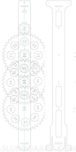
Furthermore, I never had time to clean up the schematics, so you may not be able to get this working without modifying some of the parts yourself. With that in mind, you can download all the parts as pdf by clicking this link.
Functions and Parts
The mechanical clock consists of several main functions. To keep the time, a pendulum oscillates from side to side. The time for one complete cycle called a period. The period time can be determined by some simple mathematical formulas, and has impact on the dimensions for the pendulum.
The pendulum does not swing by itself, and needs some sort of power applied to it. This is done by a weight, giving torque to the gear attached to the pendulum.
Giving the weight a free fall would just make the clock go very fast, and having to rewind the weight every 2 seconds. Therefore, an escape mechanism is required, typically being an escape lever combined with an escape gear. The details of this function will be explained later.
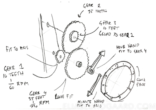
To be able to gear up or gear down the rotations done by the pendulum to actually be able to tell the time, a gear train is required. And to have the hour hand and minute hand go together correctly, additional clock gears have to be added. The latter is not a top priority in this project, because of the limited time given. Here’s a quick sketch of my initial design:
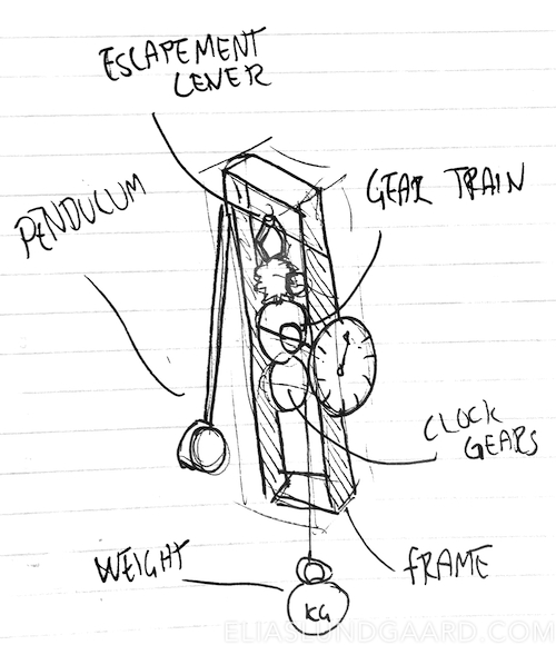
A quick sketch of my initial design
Since all these parts are codependent, designing them individually proved to be very challenging. Instead I based the overall design on Brian Law’s Youtube channel on wooden clocks.
The Escape Mechanism
Since my sources descriped the escape mechanism as the most tricky part, I figured it would be best to start here. The escape mechanism consists of a lever and a gear. The lever, connected to the pendulum, only allows the gear to do one tick per pendulum period. Here’s a gif, because it’s absolutely impossible to visualize it in your mind:
Source: Wikimedia Commons
Since I had absolutely no idea on how to model this special gear, I downloaded a Wolfram CDF demonstration model, and used the software to model the gear. I wanted the pendulum to have a period of one second. Since the escape mechanism needs two periods to move one tooth, the gear would need 30 teeth. I changed the variable in the program, and took a screen shot of it. The screen shot was then imported to Autodesk Fusion, and used as a base for sketching. As this was the critical part to finish first, I exported the .DXF and laser cut it in cardboard. Even though the cardboard was very weak and hard to fit, the prototype gave a good idea on how the system would work.
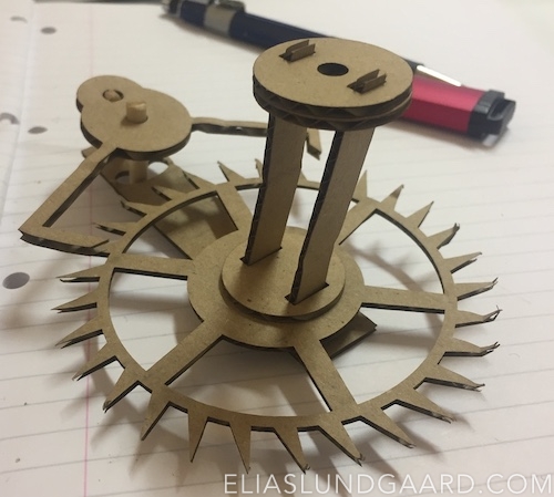
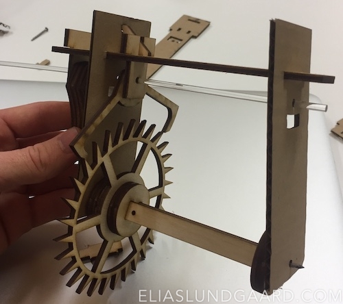
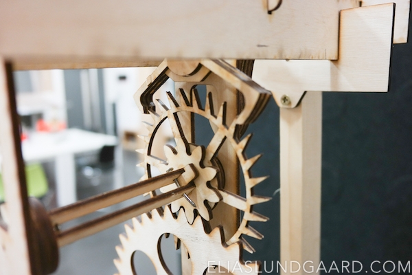
The test cut for the escapement lever.
Axis of Rotation
You’re propably wondering what those beams sticking out of the escapement are in the above picture. Since the gear train had to be connected to the same axis as the escape gear, I had to fix them in some way. To minimize the amount of glue needed, I designed a rod system, going through the centre of the gears and fixing them in position. To make them rotate, a nail would be connected in both ends, being held in place by the frame.
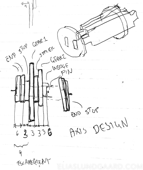
Sketch of how the axes are fixed without glue.
By adding two ”end stops”, the friction area against the frame will be minimized. The end stops are fitted on the beams through two square holes with a fitting of -0.2 mm. This makes them just fit on the beams, holding them together without any need for glue. The ends also allows for a nail to go through. The ”stop” makes sure the first gear goes to a fixed position. A ”spacer” is then added, making sure the ”gear 2" does not interact with the other gear. A wedge is then added to the end, and a pin keeps the structure fixed. Stability is very important in this design, since any flexibility could make the gears jump out of place. Two end stops are then added to the other end, giving the rod an axis of rotation. Again I designed the initial idea in Fusion 360, and made sure that the spacing fit with the escapement gear previously made.
Upper frame
One thing is to create individual parts that fits together on paper. Another is to actually have them fixed and fit in a specific location, and having all parts move together correctly. This proved to be the most challenging part of the project, making the over 20 parts of the upper part fit into the same frame.
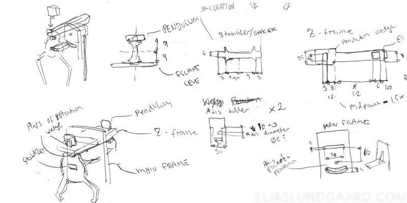
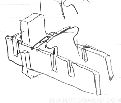
Initial sketch of the upper frame including escapement lever.
The initial sketch is shown above, and features two ”axis holders”, through which the rotational axis of the esaape lever and pendulum goes. These are fixed on the ”Z-frame”, the horizontal part, with a ”wedge”, also used in the axis. To fix the escape lever to the pendulum, a ”stabilizer/spacer” is used, also making sure that both the pendulum and the lever are constantly perpendicular to the Z-frame. The ”main frame” has a rectangular cut for the Z-frame, and a cut arc to allow for the pendulum to swing. This was where laser cutting was very helpful for the project. Since there where so many parts that had to fit together, laser cutting allowed me to quickly confirm or deny whether the parts fitted. By making this prototype, I found out the stabilizer was 3mm too small, and that the frame needed some kind of vertical stabilizer.
Initial sketch of the upper frame including escapement lever.
The Pendulum
I will not go through the mathematics of pendulums. However, Wikipedia has a good introduction on the area:
The period of swing of a simple gravity pendulum depends on its length, the local strength of gravity, and to a small extent on the maximum angle that the pendulum swings away from vertical, θ, called the amplitude. It is independent of the mass of the bob. If the amplitude is limited to small swings.
Therefore, the length of the pendulum is the only thing that matters. To get a one second period swing time, the arm needs to be one meter. I found a 8 mm wooden rod of one meter, and designed a fixture which a encapsulates the stick, by having 3 hollow 3mm parts, and two outer parts. The design turned out a bit different when doing it in fusion, since some cool details could easily be added. After a quick cardboard prototype, I printed a wooden version of the pendulum fixture and escape lever.
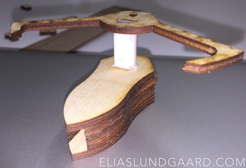
The pendulum fixture. Pendulum rod goes into the hole.
The Gear Train
Since I had already made the axes for the gears, this part was mainly just about calculating how many gears should be included, and how many teeth they should have. The calculation was as follows:
- The escape lever allows the escape gear to move 1 tooth per second period. Therefore, the escape gear does 1 RPM (rotation per minute).
- I want the final gear of the gear train to work as the minute hand on a clock. The minute hand does one rotation an hour, or 1/60 RPM.
- A simple way is to assume the gear ratio of all gears to be the same, so the train will consist of ”segments” of spur gears » Without going in depth with the calculations, the formula I used is:
$$RPM = {{RPM_{start}} \over R^N}$$
- Where RPMstart is 1, RPM is 1/60, R is the gear ratio and N is the number of gears.
- If the gear train consists of 3 large gears, the ratio has to be 1:3.9, and if I use 4 gears, the ratio has to be 1:2.78
- Since i don’t want too many gears , I chose 3 gears.
Using this method, I would need 3 small gears with 10 teeth, and 3 large with 39 teeth. I used Geargenerator to model this setup, to make sure my calculations were right. I then proceeded to model the gears in Fusion 360 using the built-in spur gear generator, choosing a module of 4 and a pressure angle of 27°. Since a lot of spacers and end pieces would be needed for the gear train, I took use of some of the space in the gears to cut out the pieces. This would save some material. With the gear train specified, the frame could be finished.
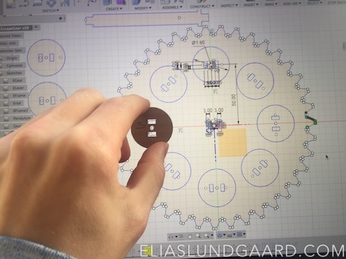
The gear in Fusion with a cut-out of the spacer.
Frame
Since the upper frame was already finished, the only thing need was to make holes for the axes to go through. To make sure the gears fitted, I imported the .DXF files to Adobe Illustrator, and aligned them with the holes.
Since the frame and the gears made up most of the material required for the clock, I wanted to make sure everything fit before cutting. Before cutting the frame, I added cut-outs for stabilizers in the bottom, and an overhang in the top, to allow for hanging on the wall. I then cut some gears and the frame in cardboard to make sure they fit. Since I also would need a clock face to actually tell the time, I designed one in Illustrator while waiting in the laser cutting queue. I also put the pendulum in place with nails.
Aligned vector files. Everything seems to fit!
The Clock Gears
Note: I made a miscalculation here. A kind reader notified me the following: As you mentions on the webpages, you used two gears of ratio 1:3.5 which gives
10/35*10/35 = 1:12.25final ratio instead of 1:12. As result your clock loss an hour each 2 days. The solution should be to use correct clock gears configuration to fit the ration 1:12. To find the gear configuration is not easy but you can trust me the25/75*20/80fits well. There is also possible to use smaller gears,5/15*4/16or15/45*12/48or10/30*8/32. Here’s an updated GearGenerator.
I now had most things required for making the final clock. Pendulum, escape mechanism, gear train, main frame and clock face were all finished and ready for a final print. However, to tell the time correctly, an hour hand is also needed. Doing the same calculations as for the gear train, a gear ratio of 1:3,5 , using two gears to get the final gear doing one rotation each 12 hours (1/720 RPM) was determined. Again, the gears were modelled using Fusion. These gears would not be attached to the gear train, but directly behind the clock face to have two different rotations on the same axis (using some fittings).
The gears were made quite quickly since it was the same approach as in the gear train. When finished, I could laser cut the majority of the clock files.
Exploded view of the clock face. Glue was used to fix the rotation of the smaller gears to the larger gears.
Assembling the Clock
Now it’s time for assembly!
The Stand
Since the pendulum is longer than the clock itself, it was not a possibility to have it standing by itself. With some help, I got a stand with an appropriate height built. I immediately regretted making the top sets of the frame round, since this would be much harder to get completely level. After many design ideas, the final design turned out to be a system made up by two ”holders”, attached opposite of each other to the stand.
Two rectangular cut-outs are made in each holder, keeping the crossbeam in place and level. The crossbeams also has two 3mm cut-outs, allowing the upper frames to slide down on it. This will keep the clock in place.
Pendulum Weight
The pendulum needs a tip weight to be able to rotate the escape gear. I figured that since I would need to do a lot of testing, the easiest way to this would be by using a Coca Cola bottle, and attaching the cap to the pendulum arm. This way the bottle can be removed and weight added without further disassembly.
Power Weight
The power weight is attached to one of the gear axes, and powers the clock. In my case, I will use a string attached to a water bottle, which is winded around a pulley. The pulley is fixed to one of the gear axes, and its location determines how often the clock needs to be re-winded. For instance, if the pulley is fixed at the escape gear, and winded three times, it will take 3 rotations for it to unwind completely. Therefore, the clock will have to be re-winded every 3 minutes. If the pulley is attached to the minute gear and winded 3 times, it will consequently need a rewind every 3 hours. The price for this is torque it requires the sixty times as much torque to rotate the minute gear as compared to the escape gear. Therefore, I will place the pulley at the minute gear, and attach extra weight.
The pulley with a string attached. The coke bottle is at the other end, being worked on by gravity.
Testing the Clock
After the last couple of pieces where laser cut, the final assembly could now begin. I added the clock hands the hour hand cut in black acrylic and minute hand cut in wood colored red. The hour hand was fixed to the hour gear, and the minute hand to the axis (the screw), thereby moving them independently.
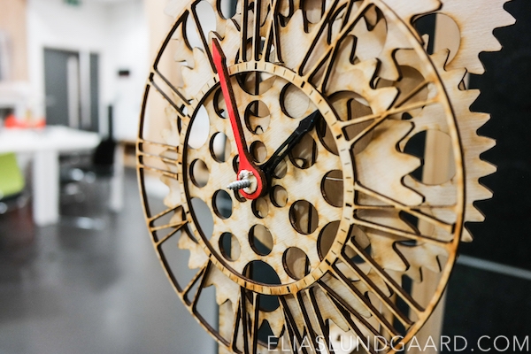
The assembled clock face
The stand was assembled with assistance but proved to be hard to level due to the design. Since I had very short time on the laser cutter, I didn’t get to test it properly. This resulted in the fitting being a bit too loose, allowing the stand to move too much. Aligning the vertical plates to level the clock also proved to be challenging. To combat this, I should have made cut outs in both the vertical and horizontal, making them fit. The Coca Cola bottle with stones for weight was added to the pendulum. This was achieved by cutting a 8mm hole on the bottle cap, fitting it on the rod and adding a wooden stop with a nail to keep it in place. After these small additions were made, the clock could finally be tested. Moving the pendulum to a extreme position and letting it go, made the escape lever ”tick” three times. All the gearing seemed to move correctly. Next i tried to add weight to the pulley to make the clock go automatically. Unfortunately no matter how much weight I added, I couldn’t seem to make it go. I narrowed the problem down to the escape mechanism. Unfortunately, the mechanism was not stable enough to move the pendulum. Since the spacer between the pendulum and the lever was made of acrylic, it allowed for too much movement between the parts. The lever itself was too thin, making it deform when exposed to pressure and the escape gear was too week, getting its teeth grinded down by the lever. After hours of modification, I realised that I wouldn’t be able to make it run without designing a new lever escape and pendulum. Since I was short of time, I didn’t get around doing this. Instead I used a drill to prove that the rest of the clock worked.
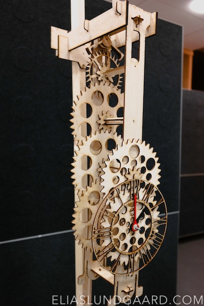
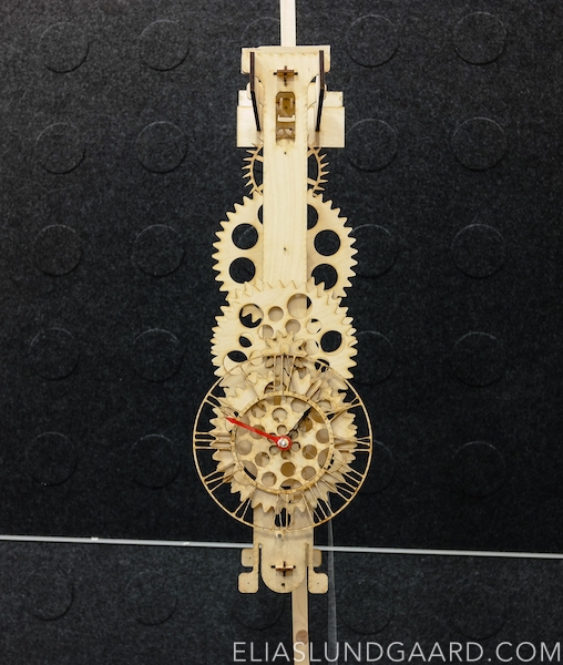
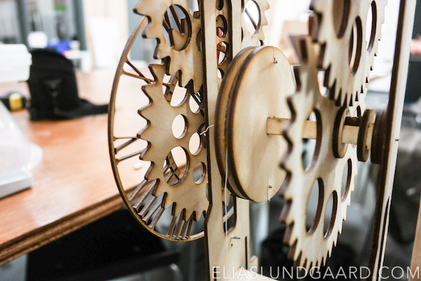
The finalized clock, in all its glory!
Future Improvements
Through the prototyping phase many small changes had to be made because of miscalculations, instability issues and fitting problems. A main problem with using fittings is that the wood used had small differences in thickness, depending on what sheet was used. This made it hard to get the same result at different times. The wall hanging method could also be significantly improved, making the clock more stable, easier to mount, and in level. The pendulum proved to be a major annoyance, since its swing amplitude near the bottom of the clock is very large, making it hard to fix the clock from the bottom. A final challenge is to make the clock work by it self. This would require a redesign of the lever escape and gear, using thicker (6 mm) wood, making the structures more stable, and making the spacer of solid wood. Furthermore, the Escape gear may need some treatment to make it harder, avoiding wear.
The End?
This sure was a fun and challenging project. I’m still a bit bummed over never getting the escape lever to properly, but still, given the time period I’m really satisfied. Unfortunately I couldn’t bring the clock home from England, so it’s probably lying around somewhere at Lancaster University, bringing inspiration for the new student’s projects.